InGaAs Balanced Photodetector (BPD)
Compact Single-Power-Supply Version | Product Manual
Document Date | 2025-09 |
Version | English Translation V0.2 |
Standard Models | FX-BPD-50M / 100M / 200M / 400M / 500M / 800M |
Product Overview:
The BPD low-noise balanced photodetector uses a pair of matched photodetectors and differential output to reduce common-mode noise and relative intensity noise, improving reception quality for weak optical signals and coherent beat signals. It is suitable for precision optical measurement and fiber sensing receiver front ends.
Key Features:
• Differential optical reception helps suppress common-mode noise, RIN noise, and background interference.
• Low-noise and high-sensitivity reception for weak signals, interferometric signals, and coherent signals.
• Can be used as a receiver module for OCT, OFDR, DAS, FMCW LiDAR, and optical communication testing.
Applications:
• Coherent detection, interferometric measurement, weak-light detection, and precision optical experiments.
• Receiver front ends for OCT, OFDR, DAS, and fiber sensing systems.
• FMCW wind LiDAR, coherent optical communication, and optical device testing.
· Confirm the bandwidth: 50 MHz, 100 MHz, 200 MHz, 400 MHz, 500 MHz, or 800 MHz.
· Confirm the output coupling mode: AC coupling is default; DC coupling can be customized by project.
· Confirm the RF output load.
· If customized gain, low-frequency cutoff, or output swing is required, please confirm before purchase.
Wavelength Range | 900 to 1700 nm |
Bandwidth Configuration | 3 kHz to 50 MHz / 100 MHz / 200 MHz / 400 MHz / 500 MHz / 800 MHz (standard products). Custom bandwidth is available up to less than 1 GHz; for 1 GHz to 5 GHz bandwidth, refer to the high-bandwidth BPD. |
Output Type | AC coupling (default) or DC coupling (customizable) |
Power Supply | 5 VDC ± 0.25 V single power supply |
Optical Fiber Interface | FC flange; fiber pigtail can be customized |
RF Output Interface | SMA |
Main Body Size | 55 × 55 × 20 mm |
Note: The parameters in this manual are standard values or typical values. Special bandwidth, gain, coupling mode, low-frequency cutoff, interface type, and output swing are subject to the order specification.
Parameter | Specification |
Photosensitive Material | InGaAs |
Wavelength Range | 900 to 1700 nm |
Dark Output Noise | ±12 mVpp, ±2 mVrms (typical) |
Output Offset Voltage | ±2 mV (typical) |
Output Type | AC (default) or DC coupling |
Common-Mode Input Power Threshold | 5 mW per detector (typical) |
Damage Optical Power Threshold | 15 mW |
Model | Bandwidth* | Typical Gain (Customizable) |
FX-BPD-50M | 3 kHz to 50 MHz | 100 kV/A |
FX-BPD-100M | 3 kHz to 100 MHz | 60 kV/A |
FX-BPD-200M | 3 kHz to 200 MHz | 25 kV/A |
FX-BPD-400M | 3 kHz to 400 MHz | 10 kV/A |
FX-BPD-500M | 3 kHz to 500 MHz | 10 kV/A |
FX-BPD-800M | 3 kHz to 800 MHz | 2 kV/A |
Note: The low-frequency cutoff can be customized. Standard bandwidth and gain follow this table. Final specifications are subject to the order specification and factory test conditions.
Item | Specification / Description |
Optical Fiber Interface | FC flange; fiber pigtail can be customized |
RF Output Interface | SMA |
Power Supply | 5 VDC ± 0.25 V |
Operating Temperature | 0 to 50 °C (non-condensing) |
Storage Temperature | -40 to 70 °C (non-condensing) |
RF Output Item | Specification / Description |
Output Impedance | 50 Ω |
Maximum Output Voltage Swing | ±3.6 V (@ High-Z, customized; confirm before purchase) |
Load Note | With a 50 Ω input impedance, the output swing is approximately halved. |
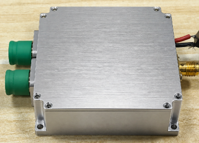
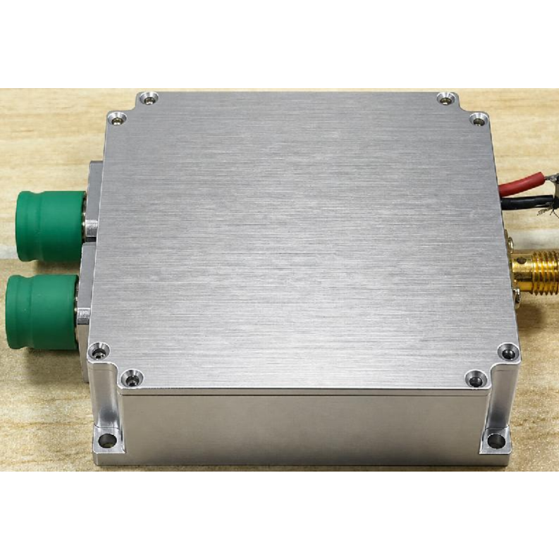
Figure 1. Product appearance.
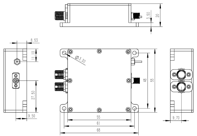
Figure 2. Mechanical dimensions (unit: mm).
FX-BPD-[BW]-[CPL]-[IF]-[OPT]
Field | Code / Option | Description |
BW | 50M / 100M / 200M / 400M / 500M / 800M / CUS | Bandwidth class. CUS = project customized. |
CPL | AC / DC | Output coupling mode. AC is default. |
IF | FC / PIGTAIL | Optical interface: FC flange or fiber pigtail. |
OPT | GAIN / SWING / LF / CUS | Customized gain, output swing, low-frequency cutoff, or other options. |
Confirmation Item | Recommended Description |
Bandwidth and Gain | Confirm the frequency range, expected optical power, required noise margin, and gain. |
Coupling Mode | AC coupling is standard. DC coupling and low-frequency cutoff should be confirmed in advance. |
RF Load | Confirm whether the receiving end is High-Z or 50 Ω to evaluate output swing. |
· FX-BPD-200M-AC-FC: 200 MHz, AC coupling, FC flange interface.
· FX-BPD-400M-DC-PIGTAIL-CUS: 400 MHz, DC coupling, pigtail interface, customized configuration.
· FX-BPD-500M-AC-FC-GAIN: 500 MHz, AC coupling, customized-gain version.
Note: Unless otherwise specified, noise, gain, bandwidth, saturation optical power, output swing, and similar values in this manual are typical values or standard configurations. Different loads, coupling modes, connectors, customized gains, and test conditions may affect final specifications.

Long Press to Scan QR Code
Scan QR Code