High-Bandwidth Balanced Photodetector (BPD)
Compact Single-Power-Supply Version | Product Manual
Document Date | 2026-05 |
Version | English Translation V0.1 |
Standard Models | FX-BPD-1G / 1.5G / 2G / 3G / 5G |
Product Overview:
The GHz high-speed BPD balanced photodetector is designed for high-speed coherent detection and broadband optoelectronic conversion. It offers bandwidth options such as 1GHz, 1.5GHz, 2GHz, 3GHz, and 5GHz, supporting high-speed beat signals, weak differential signals, and high-frequency optical communication signals.
Key Features:
• GHz-level high-speed bandwidth for broadband optical signal measurement and coherent reception.
• Low-noise differential optical reception and high common-mode rejection help improve signal-to-noise ratio.
• Suitable for OCT, OFDR, DAS, FMCW LiDAR, and coherent communication experiments.
Applications:
• High-speed coherent detection, beat-note detection, and optoelectronic conversion testing.
• High-speed fiber sensing systems such as OCT, OFDR, and DAS.
• FMCW LiDAR, coherent optical communication, and high-speed optical device testing.
· Confirm the bandwidth: 1 GHz, 1.5 GHz, 2 GHz, 3 GHz, or 5 GHz.
· For high-bandwidth models, confirm the 50 Ω RF load, cable bandwidth, and receiving-instrument bandwidth.
· AC coupling is default; DC coupling can be customized by project.
· If customized gain or output swing is required, please confirm before purchase.
Wavelength Range | 900 to 1700 nm |
Bandwidth Configuration | 100 kHz to 1 GHz / 1.5 GHz / 2 GHz / 3 GHz / 5 GHz (standard products). Low-frequency cutoff and special bandwidth can be customized by project. |
Output Type | AC coupling (default) or DC coupling (customizable) |
Power Supply | 5 VDC ± 0.25 V single power supply |
Optical Fiber Interface | Two FC/APC fiber pigtails. Other pigtail connector types can be customized. |
RF Output Interface | SMA, 50 Ω output. A high-bandwidth 50 Ω cable is recommended for the 5 GHz configuration. |
Main Body Size | 50 × 38 × 20 mm (standard compact housing; see outline drawing for mounting dimensions) |
Note: The parameters in this manual are standard values or typical values. Special bandwidth, gain, coupling mode, low-frequency cutoff, interface type, and output swing are subject to the order specification.
Parameter | Specification |
Photosensitive Material | InGaAs |
Wavelength Range | 900 to 1700 nm |
Output Offset Voltage | ±5 mV (typical) |
Output Type | AC (default) or DC coupling |
Common-Mode Optical Power Threshold | 2 mW per detector |
Damage Optical Power Threshold | 10 mW per detector |
Model | Dark Output Noise | Bandwidth* | Typical Transimpedance Gain |
FX-BPD-1G | ±15 mVpp; ±2 mVrms | 30 kHz to 1 GHz | 20 kV/A |
FX-BPD-1.5G | ±15 mVpp; ±2 mVrms | 30 kHz to 1.5 GHz | 15 kV/A |
FX-BPD-2G | ±20 mVpp; ±3 mVrms | 100 kHz to 2 GHz | 10 kV/A |
FX-BPD-3G | ±20 mVpp; ±3 mVrms | 100 kHz to 3 GHz | 5 kV/A |
FX-BPD-5G | ±20 mVpp; ±3 mVrms | 100 kHz to 5 GHz | 2 kV/A |
Note: The low-frequency cutoff can be customized. Gain, noise, saturation optical power, and output swing of high-bandwidth models vary with package, load, cable, coupling mode, and test conditions. Final specifications are subject to the order specification and factory test conditions.
Item | Specification / Description |
Optical Fiber Interface | Two FC/APC fiber pigtails; FC/PC or LC/PC fiber pigtails can be customized. |
RF Output Interface | SMA. For 3 GHz / 5 GHz models, high-bandwidth 50 Ω cables are recommended and adapters should be minimized. |
Power Supply | 5 VDC ± 0.25 V. A low-ripple linear supply or verified low-noise supply is recommended. |
Output Coupling | AC coupling is default. DC coupling, low-frequency cutoff, and output swing can be customized. |
Operating Temperature | 0 to 40 °C (non-condensing) |
Storage Temperature | -40 to 70 °C (non-condensing) |
RF Output Item | Specification / Description |
Output Impedance | 50 Ω |
Maximum Output Voltage Swing | ±1.0 V (@ High-Z, typical). High-bandwidth customized configurations must be confirmed before purchase. |
Load Note | With a 50 Ω input impedance, output swing is approximately halved. Maintain 50 Ω matching at the test end. |
High-Frequency Link Note | For 3 GHz / 5 GHz, use short cables, reduce adapters, and confirm bandwidth margin of the oscilloscope or spectrum analyzer. |
Confirmation Item | Recommended Description |
Optical Power Balance | Match the two input optical powers as closely as possible. Under strong common-mode signals, reserve margin for CMRR and output swing. |
RF Termination and Bandwidth | The receiving end, cable, adapters, and instrument bandwidth must cover the target frequency. Unterminated outputs or overly long cables may introduce reflections. |
Power Supply and Grounding | For high-bandwidth tests, single-point grounding is recommended. Keep the module away from switching supplies, strong RF interference sources, and high-current pulse lines. |
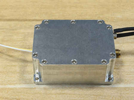
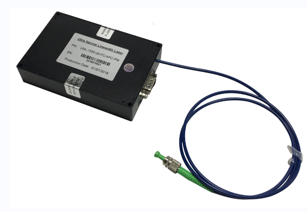
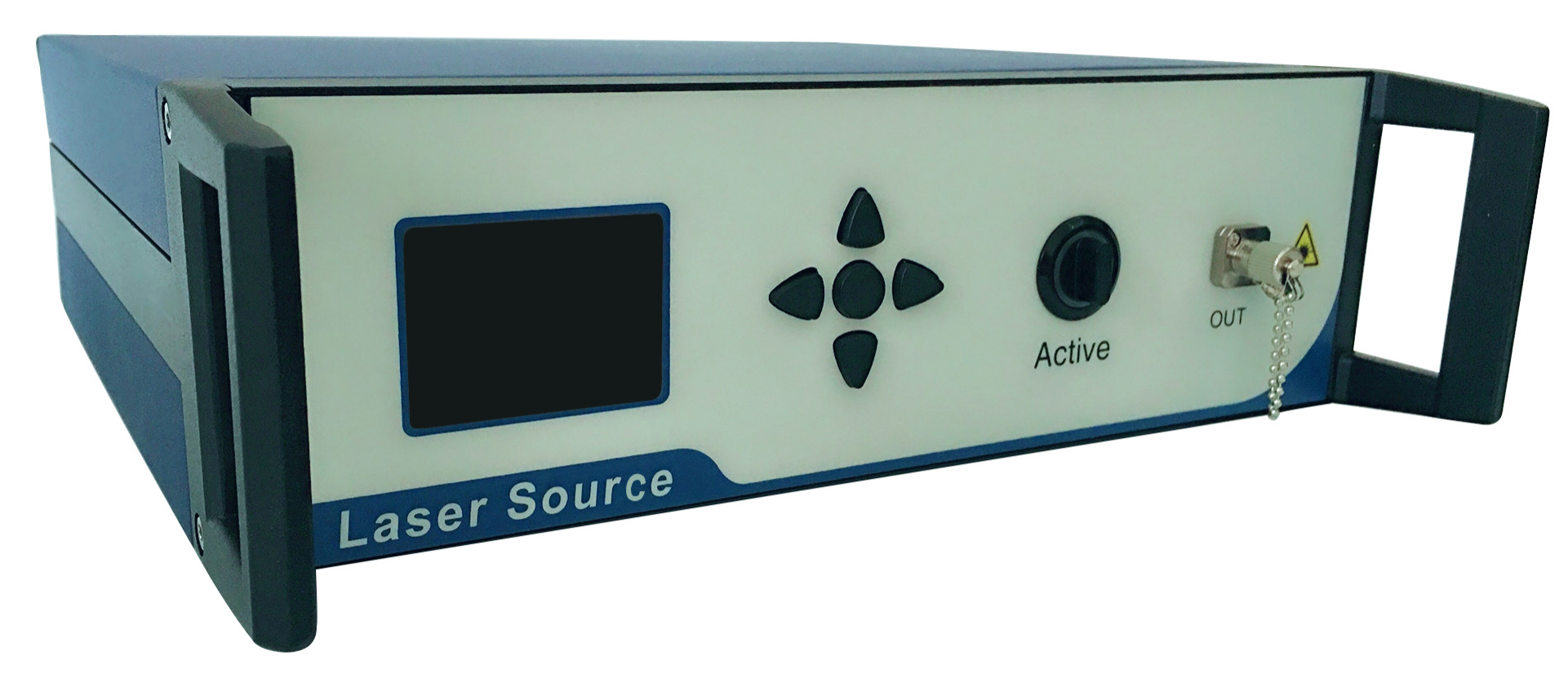
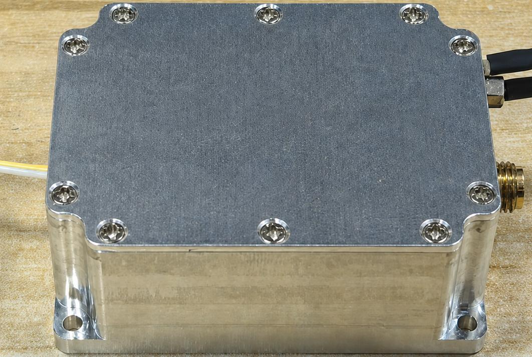
Figure 1. Product appearance.

Figure 2. Mechanical dimensions (unit: mm).
FX-BPD-[BW]-[CPL]-[IF]-[OPT]
Field | Code / Option | Description |
BW | 1G / 1.5G / 2G / 3G / 5G / CUS | Bandwidth class. CUS = project customized. |
CPL | AC / DC | Output coupling mode. AC is default. |
IF | FA / CUS | FC/APC; other customized options. |
OPT | GAIN / SWING / LF / CUS | Customized gain, output swing, low-frequency cutoff, or other options. |
Confirmation Item | Recommended Description |
Bandwidth and Gain | Confirm the target frequency range, expected optical power, required noise margin, and transimpedance gain. |
Balanced Input Conditions | Confirm two-channel input power matching, connector type, fiber type, optical-path stability, and common-mode signal amplitude. |
Coupling Mode | AC coupling is standard. DC coupling, low-frequency cutoff, and output offset control should be confirmed in advance. |
RF Load and Instrumentation | Confirm whether the receiving end is 50 Ω or High-Z, and confirm cable, adapter, and instrument bandwidth margin. |
Mechanical Integration | Confirm mounting-hole locations, FC flange direction, SMA outlet direction, and heat dissipation conditions. |
· FX-BPD-1G-AC-FA: 1 GHz, AC coupling, FC/APC fiber pigtails.
· FX-BPD-1.5G-DC-FA-LF: 1.5 GHz, DC coupling, FC/APC fiber pigtails, customized low-frequency cutoff configuration.
· FX-BPD-5G-AC-FA-GAIN: 5 GHz, AC coupling, FC/APC fiber pigtails, customized-gain version.
Note: Unless otherwise specified, noise, gain, bandwidth, saturation optical power, output swing, and similar values in this manual are typical values or standard configurations. Different loads, coupling modes, connectors, customized gains, and test conditions may affect final specifications.

Long Press to Scan QR Code
Scan QR Code