DFB Laser DWDM / CWDM / 1310 Series
Product Manual V1.2
The FXDFB-WDM series provides fixed-channel wavelength DFB laser output for wavelength-division multiplexing applications, covering DWDM channels, CWDM channels, and 1310 nm fixed wavelength. The typical output power is 8 dBm, making it suitable for optical communication link verification, WDM device testing, optical module R&D and production, field maintenance, teaching laboratories, and OEM instrument integration.
|
Product Overview:
The DFB laser DWDM/CWDM/1310nm wavelength light source module is designed for communication-band and instrument-integration applications. It provides stable distributed feedback laser output and can be configured for ITU channels, CWDM standard wavelengths, and 1310nm or 1550nm windows.
Key Features:
• Covers common communication wavelengths including DWDM, CWDM, ITU channels, 1310nm, and 1550nm.
• Stable output and compact format for integration into test instruments, fiber sensing equipment, and laboratory platforms.
• Customizable package, interface, output power, and operating mode according to system requirements.
Applications:
• DWDM/CWDM optical communication device testing and system verification.
• Fiber sensing, coherent detection, and stable laboratory light sources.
• Optical module testing, instrument integration, research, and teaching platforms.
Standard Product Snapshot
Item | Standard configuration | Item | Standard configuration |
Product model | FXDFB-WDM | Typical output power | 8 dBm |
Wavelength type | DWDM / CWDM / 1310 nm / Custom | Channel matching | Matches the corresponding DWDM or CWDM channel wavelength |
DWDM wavelength | C01-C61 channel table, selected by order | CWDM wavelength | 1260-1650 nm channel table, including 1310 nm |
Output fiber | SMF or PM pigtail optional | Connector | FC/APC typical; project-specific customization available |
Operating temperature | 0~50°C standard; -40~75°C optional | Mechanical form | Standard modular enclosure for panel or internal equipment integration |
Note: This manual is intended for series selection. Center wavelength, output power, pigtail, connector, temperature range, package, and interface shall be subject to the final order specification and factory test report.
Positioning and Applications
The core value of this series is channel wavelength matching: the laser is supplied at the center wavelength required by the target DWDM or CWDM system so it can be used directly in WDM links, device testing, and multi-channel system integration. DWDM is suitable for high-density, multi-channel, higher-capacity scenarios, while CWDM is suitable for moderate channel counts, cost-sensitive access networks, and metro expansion.
Typical Uses
Category | Application scenario | Description |
DWDM optical links | Metro, transport, data-center interconnect, wavelength-routing link verification | Used as a specified DWDM channel source for link turn-up, receiver verification, and channel power testing. |
CWDM access and metro expansion | Access networks, enterprise private lines, campus networks, and cost-effective multi-wavelength transmission | Provides the corresponding channel wavelength for CWDM Mux/Demux or passive WDM links. |
WDM device testing | Mux/Demux, AWG, filters, OADM/ROADM, and wavelength-selective devices | Used for insertion loss, channel isolation, crosstalk, channel uniformity, and thermal drift verification. |
Optical module R&D and production | TOSA/ROSA, optical transceiver modules, boards, and receiver sensitivity testing | Serves as a fixed-wavelength reference source for module debugging, burn-in screening, and production-line testing. |
Field maintenance and commissioning | Fiber link identification, channel verification, power budget checks, and fault localization | Helps quickly confirm whether a specific DWDM or CWDM channel is available. |
Teaching laboratories and OEM integration | WDM principle demonstrations, multi-wavelength experiment platforms, and built-in sources for test instruments | Compact modular construction supports multi-channel stacking, panel integration, and secondary development. |
Key Features
DWDM channel coverage Supports DWDM channel wavelengths such as C01-C61, enabling matching with existing DWDM Mux/Demux, AWG, and optical network channels. | CWDM channel coverage Covers 1260-1650 nm project channels, including common 1270-1610 nm channels and extended wavelengths. | Added 1310 nm option 1310 nm can be ordered as CWDM Ch31 or as an independent fixed-wavelength version for 1310 nm link and device testing. |
8 dBm typical output Typical output power of 8 dBm is suitable for laboratory, production-line, and built-in reference source applications. | Good SMSR The DFB structure provides good side-mode suppression for fixed-channel identification, wavelength selection, and receiver verification. | Modular delivery Standard modular form factor in the same product family; pigtail, connector, temperature range, and electrical interface can be configured by project. |
Note: This product category focuses on DWDM / CWDM channel wavelength matching. Application descriptions are centered on WDM links, device testing, module verification, and OEM integration.
Electro-Optical Specifications
The specifications below are intended for standard selection. Actual performance may vary with channel wavelength, package version, pigtail type, heat dissipation, and drive settings, and shall be subject to the final specification and factory test report.
Symbol | Parameter | Condition / Configuration | Min. | Typ. | Max. | Unit |
Pout | Output power | Standard version | — | 8 | — | dBm |
| Output power | Conversion reference | — | approx. 6.3 | — | mW |
λc | Center wavelength | DWDM channel | — | C01-C61 | — | nm |
λc | Center wavelength | CWDM channel | — | 1260-1650; incl. 1310 | — | nm |
SMSR | Side-mode suppression ratio | DFB output | 35 | 40 | — | dB |
PER | Polarization extinction ratio | PM pigtail version | 18 | — | — | dB |
ISO | Optical isolation | Built-in isolator version | 20 | — | — | dB |
ΔP | Output power stability | After temperature control stabilizes | — | Per project specification | — | dB / % |
Vcc | Supply voltage | Standard drive interface | 4.75 | 5.0 | 5.25 | V |
Top | Operating temperature | Standard / wide-temperature optional | 0 / -40 | — | 50 / 75 | °C |
Operation, Storage and Interface
Item | Typical configuration | Optional configuration / Remarks |
Operating temperature | 0~50°C | -40~75°C wide-temperature version requires order confirmation |
Operating humidity | 5~85%RH, non-condensing | Higher humidity or outdoor environments require system-level protection |
Storage temperature | -40~85°C | Avoid strong impact, electrostatic discharge, and end-face contamination |
Output fiber | SMF single-mode pigtail | PM pigtail optional, aligned to slow axis |
Connector | FC/APC | SC/APC, LC/PC, bare fiber, or other connectors can be customized |
Control method | Modular drive and temperature-control interface | Can be adjusted according to OEM equipment interface definitions |
DWDM Channel Information
DWDM versions are selected by channel number. The table is for selection and order communication; final channel naming, allowable tolerance, and test conditions shall follow the project specification.
Channel | λ (nm) | Channel | λ (nm) | Channel | λ (nm) |
C01 | 1577.03 | C21 | 1560.61 | C41 | 1544.53 |
C02 | 1576.20 | C22 | 1559.79 | C42 | 1543.73 |
C03 | 1575.37 | C23 | 1558.98 | C43 | 1542.94 |
C04 | 1574.54 | C24 | 1558.17 | C44 | 1542.14 |
C05 | 1573.71 | C25 | 1557.36 | C45 | 1541.35 |
C06 | 1572.89 | C26 | 1556.55 | C46 | 1540.56 |
C07 | 1572.08 | C27 | 1555.75 | C47 | 1539.77 |
C08 | 1571.24 | C28 | 1554.94 | C48 | 1538.98 |
C09 | 1570.42 | C29 | 1554.13 | C49 | 1538.19 |
C10 | 1569.59 | C30 | 1553.33 | C50 | 1537.40 |
C11 | 1568.77 | C31 | 1552.52 | C51 | 1536.61 |
C12 | 1567.95 | C32 | 1551.72 | C52 | 1535.82 |
C13 | 1567.13 | C33 | 1550.92 | C53 | 1535.04 |
C14 | 1566.31 | C34 | 1550.12 | C54 | 1534.25 |
C15 | 1565.50 | C35 | 1549.32 | C55 | 1533.47 |
C16 | 1564.68 | C36 | 1548.51 | C56 | 1532.68 |
C17 | 1563.86 | C37 | 1547.72 | C57 | 1531.90 |
C18 | 1563.05 | C38 | 1546.92 | C58 | 1531.12 |
C19 | 1562.23 | C39 | 1546.12 | C59 | 1530.33 |
C20 | 1561.42 | C40 | 1545.32 | C60 | 1529.55 |
|
|
|
| C61 | 1528.77 |
Ordering example: FXDFB-WDM-DWDM-C34-8D-SM-FCAPC indicates DWDM C34 channel, typical output power 8 dBm, SM pigtail, and FC/APC connector.
CWDM Channel Information
CWDM versions are selected by channel code or center wavelength. 1310 nm is included as an optional wavelength and can be ordered as CWDM Ch31 or as a 1310 nm fixed-wavelength version.
Channel code | Center wavelength | Channel code | Center wavelength | Channel code | Center wavelength |
27 | 1270 | 39 | 1390 | 51 | 1510 |
29 | 1290 | 41 | 1410 | 53 | 1530 |
31 | 1310 | 43 | 1430 | 55 | 1550 |
33 | 1330 | 45 | 1450 | 57 | 1570 |
35 | 1350 | 47 | 1470 | 59 | 1590 |
37 | 1370 | 49 | 1490 | 61 | 1610 |
Extended / Project Channels
Channel code | Center wavelength | Channel code | Center wavelength | Channel code | Center wavelength |
54 | 1540 | 63 | 1630 | 62 | 1620 |
56 | 1560 | 65 | 1650 | 625 | 1625 |
58 | 1580 | 26 | 1260 | 342 | 1342 |
60 | 1600 | 264 | 1264 | 635 | 1635 |
Note: Blue-band, extended, or project channels can be confirmed according to device availability, temperature-control solution, and order quantity. Output power, SMSR, and temperature range may vary by wavelength.
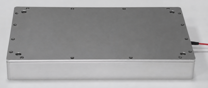
Mechanical Design
The product uses the same-family standard modular enclosure. Mechanical dimensions, mounting hole positions, pigtail direction, and panel markings shall follow the actual order version and engineering drawings.

Figure: Mechanical outline drawing. Units and tolerances are subject to the factory drawing.
Ordering Information
FXDFB-WDM - [Type] - [Channel/Wavelength] - 8D - [Fiber] - [Connector] - [Opt]
Field | Code | Description |
Type | DWDM / CWDM / FIX | DWDM channel, CWDM channel, or fixed center wavelength. |
Channel/Wavelength | C34 / 31 / 1310 / CUS | Enter a DWDM channel, CWDM channel code, center wavelength value, or custom code. |
Power | 8D | Typical output power 8 dBm. |
Fiber | SM / PM | SM = single-mode pigtail; PM = polarization-maintaining pigtail. |
Connector | FCAPC / CUS | Standard FC/APC; other connectors may be specified by project. |
Opt | WD / OEM / CUS | Wide-temperature, OEM interface, pigtail length, labeling, or other special requirements. |
• FXDFB-WDM-DWDM-C34-8D-SM-FCAPC: DWDM C34 channel, typical output power 8 dBm, SM pigtail, FC/APC.
• FXDFB-WDM-CWDM-31-8D-SM-FCAPC: CWDM Ch31, center wavelength 1310 nm, typical output power 8 dBm.
• FXDFB-WDM-CWDM-55-8D-PM-FCAPC: CWDM Ch55, center wavelength 1550 nm, PM pigtail, FC/APC.
• FXDFB-WDM-FIX-1310-8D-SM-CUS: Fixed 1310 nm wavelength, connector and pigtail customized by project.

Long Press to Scan QR Code
Scan QR Code