Polarization-Diversity Coherent Receiver Module
Single-Power-Supply Version | Product Manual
Document Date | 2025-08 |
Version | English Translation V0.2 |
Standard Models | FX-PDR-50M / 100M / 200M / 400M / 500M / 800M |
Product Overview:
The PDR polarization-diversity coherent receiver module is designed for coherent detection systems that require stable reception of optical signals with varying polarization states. It reduces the impact of polarization fading and provides a polarization-diversity front end for OFDR, DAS, FMCW LiDAR, and coherent optical communication systems.
Key Features:
• Supports dual-polarization coherent reception for fiber links with changing polarization states.
• Polarization-diversity architecture improves polarization-independent detection and reception stability.
• Easy to integrate with local oscillator lasers, balanced detectors, data acquisition cards, and demodulation algorithms.
Applications:
• Coherent fiber sensing systems such as OFDR and DAS.
• FMCW LiDAR, coherent wind measurement, and precision coherent measurement.
• Coherent optical communication, polarization-multiplexed reception, and research system integration.
· Confirm the bandwidth: 50 MHz, 100 MHz, 200 MHz, 400 MHz, 500 MHz, or 800 MHz.
· Confirm the output coupling mode: AC coupling is default; DC coupling can be customized by project.
· Select FC flange or fiber pigtail according to the system interface.
· Confirm the RF output load.
· If customized gain, low-frequency cutoff, or output swing is required, please confirm before purchase.
Wavelength Range | 900 to 1700 nm |
Bandwidth Configuration | 3 kHz to 50 MHz / 100 MHz / 200 MHz / 400 MHz / 500 MHz / 800 MHz (standard products). Custom bandwidth is available up to less than 1 GHz; for 1 GHz to 5 GHz bandwidth, refer to the high-bandwidth PDR. |
Output Type | AC coupling (default) or DC coupling (customizable) |
Power Supply | 5 VDC ± 0.25 V single power supply |
Optical Fiber Interface | FC flange (default) or fiber pigtail |
RF Output Interface | SMA |
Main Body Size | 120 × 100 × 18 mm |
Note: The parameters in this manual are standard values or typical values. Special bandwidth, gain, coupling mode, low-frequency cutoff, interface type, and output swing are subject to the order specification.
The internal optical path consists of a polarization-diversity structure and two balanced detection outputs. Abbreviations: SIG = Signal input; LO = Local Oscillator input; PBS = Polarization Beam Splitter; PM OC = Polarization-Maintaining Optical Coupler; BPD = Balanced Photodetector.
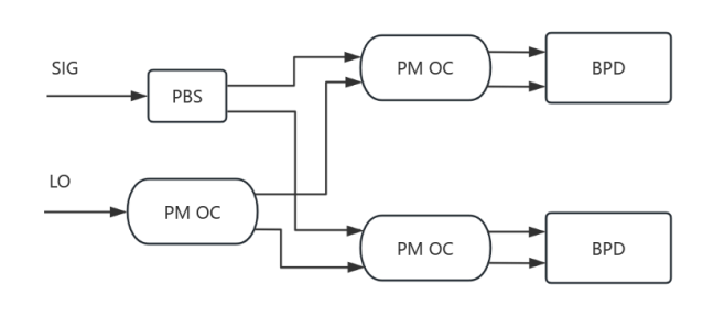
Figure 1. Principle block diagram of the polarization-diversity receiver module.
Parameter | Specification |
Photosensitive Material | InGaAs |
Wavelength Range | 900 to 1700 nm |
Dark Output Noise | ±10 mVpp, ±2 mVrms (typical) |
Output Offset Voltage | ±3 mV (typical) |
Output Coupling Type | AC (default) or DC coupling |
Common-Mode Optical Power Threshold | 5 mW per detector (typical) |
Damage Optical Power Threshold | 15 mW |
Model | Bandwidth* | Typical Gain (Customizable) |
FX-PDR-50M | 3 kHz to 50 MHz | 100 kV/A |
FX-PDR-100M | 3 kHz to 100 MHz | 60 kV/A |
FX-PDR-200M | 3 kHz to 200 MHz | 25 kV/A |
FX-PDR-400M | 3 kHz to 400 MHz | 10 kV/A |
FX-PDR-500M | 3 kHz to 500 MHz | 10 kV/A |
FX-PDR-800M | 3 kHz to 800 MHz | 2 kV/A |
Note: The low-frequency cutoff can be customized. Final specifications such as gain are subject to the order specification and factory test conditions.
Item | Specification / Description |
Optical Fiber Interface | FC flange or fiber pigtail |
RF Output Interface | SMA |
Power Supply | 5 VDC ± 0.25 V |
Operating Temperature | 0 to 50 °C (non-condensing) |
Storage Temperature | -40 to 70 °C (non-condensing) |
RF Output Item | Specification / Description |
Output Impedance | 50 Ω |
Maximum Output Voltage Swing | ±3.6 V (@ High-Z, customized; confirm before purchase) |
Load Note | With a 50 Ω input impedance, the output swing is approximately halved. |
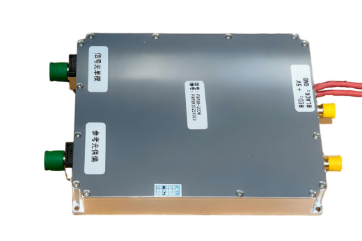
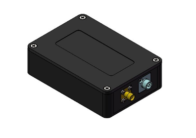
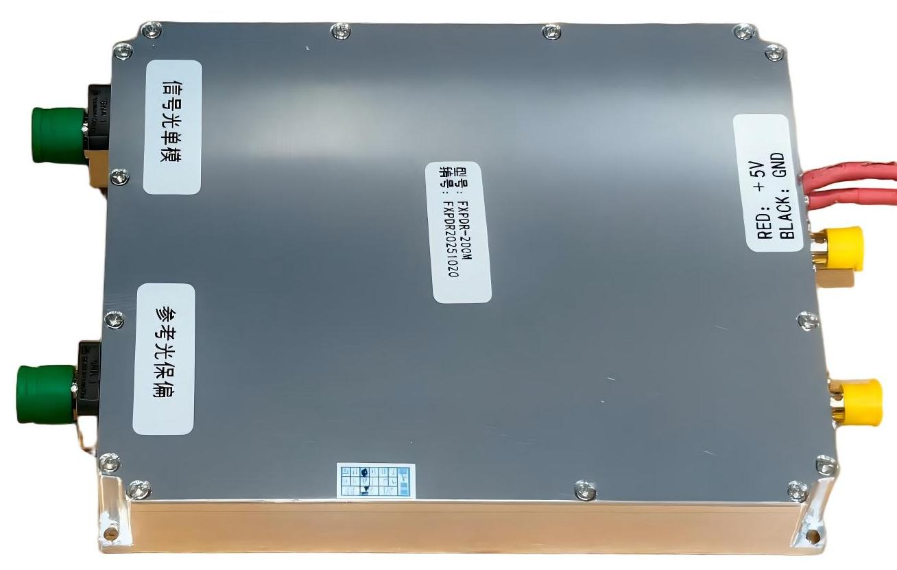
Figure 2. Product appearance.

Figure 3. Mechanical dimensions (unit: mm).
FX-PDR-[BW]-[CPL]-[IF]-[OPT]
Field | Code / Option | Description |
BW | 50M / 100M / 200M / 400M / 500M / 800M / CUS | Bandwidth class. CUS = project customized. |
CPL | AC / DC | Output coupling mode. AC is default. |
IF | FC / PIGTAIL | Optical interface: FC flange or fiber pigtail. |
OPT | GAIN / SWING / LF / CUS | Customized gain, output swing, low-frequency cutoff, or other options. |
Confirmation Item | Recommended Description |
Bandwidth and Gain | Confirm the target signal frequency range, expected optical power, and required transimpedance gain. |
Coupling Mode | AC coupling is standard. DC coupling and low-frequency cutoff should be confirmed in advance. |
RF Load | Confirm whether the receiving end is High-Z or 50 Ω to evaluate output swing. |
Optical Input Interface | FC flange / pigtail. |
· FX-PDR-200M-AC-FC: 200 MHz, AC coupling, FC flange interface.
· FX-PDR-400M-DC-PIGTAIL-CUS: 400 MHz, DC coupling, fiber pigtail, customized configuration.
· FX-PDR-500M-AC-FC-GAIN: 500 MHz, AC coupling, FC flange interface, customized gain.
Note: Unless otherwise specified, noise, gain, bandwidth, saturation optical power, output swing, and similar values in this manual are typical values or standard configurations. Different loads, coupling modes, connectors, customized gains, and test conditions may affect final specifications.

Long Press to Scan QR Code
Scan QR Code